
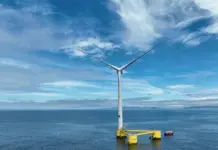



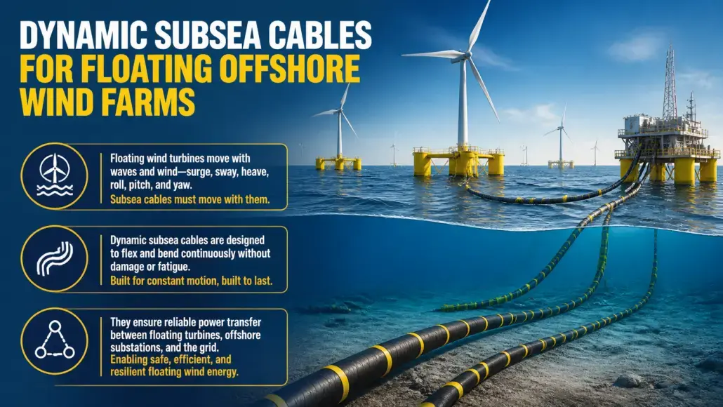
Exporting electrical power from fixed-bottom offshore wind turbines relies on static subsea cables buried beneath the seafloor. Once settled into trench beds, these traditional cables experience negligible mechanical movement. Floating offshore wind completely alters this operating paradigm. Because floating foundations surge, sway, heave, roll, pitch, and yaw under continuous environmental forces, the subsea power conduits connecting platforms to one another and to offshore substations must function as flexible, dynamic lifelines.
Dynamic subsea cables are exposed to perpetual wave action, subsurface marine currents, and platform motions throughout their twenty-five-year design life. A single dynamic cable can undergo over one hundred million bending cycles during its operational lifespan. At the same time, the conductor must transport power at sixty-six kilovolts for inter-array links and up to two hundred and twenty or three hundred and twenty kilovolts for high-voltage alternating current or direct current export systems. PowerGen Advancement notes that combining intense cyclic fatigue with severe thermal gradients and high electrical stress represents one of the most demanding engineering frontiers in offshore renewable energy.
In floating arrays, mechanical failure of a dynamic cable halts power transmission from multi-megawatt turbines and requires complex offshore repair campaigns using specialized deepwater construction vessels. Ensuring mechanical endurance and electrical integrity under continuous motion is therefore essential to commercial floating wind economics.
Structural Anatomy of Dynamic Cable Cross-Sections
Standard subsea power cables use solid or extruded metallic barriers, typically lead sheaths, to prevent moisture ingress into high-voltage insulation layers. However, lead exhibits low fatigue resistance and easily cracks when subjected to cyclic bending, allowing water to penetrate the cross-section and triggering electrical treeing breakdown. Dynamic subsea cables resolve this limitation by replacing conventional lead sheathing with fatigue-resistant metallic barriers or dry, semi-wet construction architectures.
Cable cross-sections feature several specialized mechanical layers designed to decouple mechanical loads from the electrical conductors:
- Segmented copper or aluminum conductors arranged in compact, stranded profiles that slide slightly under bending to minimize axial stress.
- Cross-linked polyethylene insulation formulated for high dielectric endurance under fluctuating operational temperatures.
- Corrugated copper or welded aluminum sheaths that provide radial water barriers while absorbing cyclical mechanical strain without micro-cracking.
- Counter-helical layers of high-tensile galvanized steel armor wires applied in balanced torque configurations to resist tension and prevent twisting.
- Tough external polymeric sheaths made from high-density polyethylene or polyamide to shield against seawater abrasion and impact damage.
Prysmian Group accelerated commercial qualification in 2025 for its high-voltage dynamic cable systems rated up to two hundred and twenty kilovolts. Their design incorporates advanced copper conductors wrapped in patented composite armor layers that significantly reduce cable self-weight while boosting bending fatigue resistance. By eliminating heavy lead sheaths, the cable structure withstands rigorous mechanical cycles induced by rough sea states, enabling reliable power evacuation from deepwater Atlantic and North Sea floating concessions.
Mechanical qualification of dynamic cable cross-sections requires extensive physical testing under simulated offshore environments. Cable prototypes undergo millions of reversed bending cycles on full-scale tension-bend test rigs while subjected to continuous mechanical pulling forces. During these endurance trials, engineers monitor electrical resistance, partial discharge activity, and optical fiber attenuation to verify that cyclic strain does not degrade electrical insulation or crush internal fiber tubes. Passing these severe tests ensures that the composite internal structure withstands dynamic ocean fatigue over decades of continuous operation.
Hydrodynamic Configurations and Ancillary Mechanical Hardware
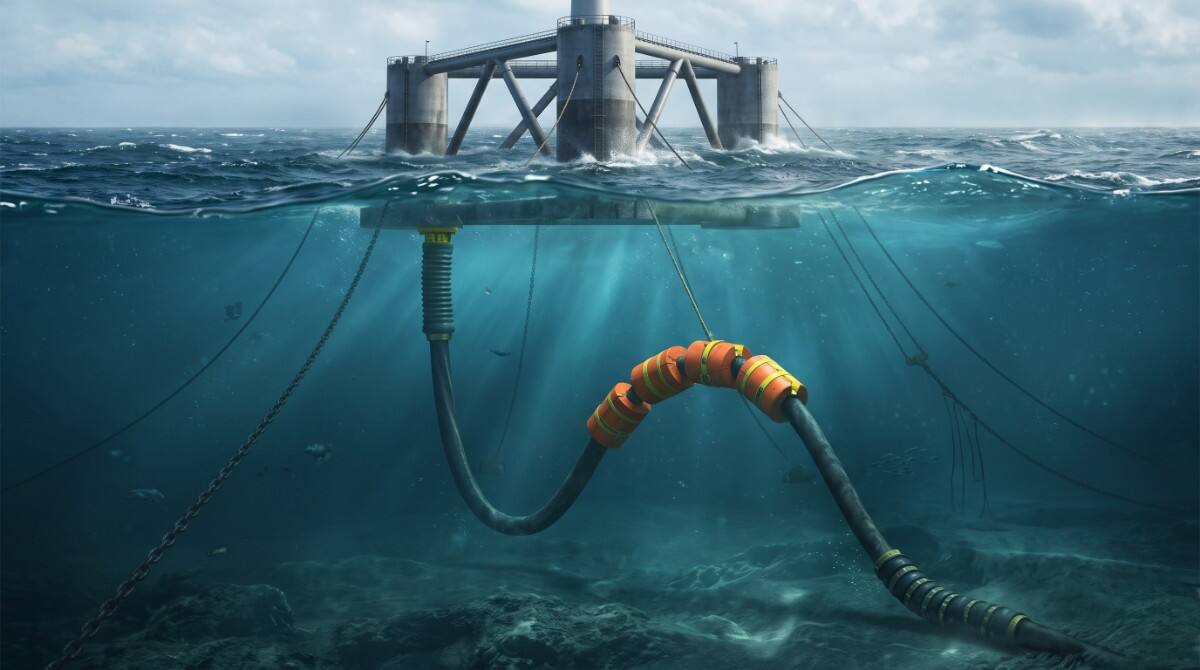
Suspending a heavy electrical cable between a moving floating hull and the stationary seabed requires an engineered hydrodynamic configuration. If hung as a simple catenary, platform heave and wave action would induce severe tension spikes at the platform hang-off and excessive compressive bending at the seabed touchdown point.
Marine engineers deploy the lazy-wave profile as the dominant global standard for deepwater floating arrays. In a lazy-wave arrangement, discrete buoyancy modules are clamped along a mid-water section of the cable, lifting it into an elevated arch. This buoyant arch acts as a mechanical spring, flexing to absorb platform excursions and ocean currents without transmitting excessive tension to the top hang-off or driving sharp bending angles at the seafloor.
Maintaining the structural integrity of dynamic subsea cables across the water column requires specialized ancillary hardware:
- Polyurethane bend stiffeners positioned at platform I-tubes or J-tubes to prevent localized over-bending and curvature concentration during heavy storms.
- Distributed buoyancy modules manufactured from syntactic foam engineered to withstand high hydrostatic pressure without crushing or water absorption.
- Subsea bend restrictors installed at the seabed touchdown zone to enforce a minimum bend radius and protect internal electrical insulation.
- Cable hang-off assemblies anchored inside the turbine hull that grip the steel armor wires and transfer axial tension into the floating foundation structure.
Trelleborg expanded its offshore manufacturing portfolio in 2025 with dynamic bend stiffener and buoyancy systems tailored for fifteen-megawatt floating platforms. Using non-linear finite element modeling and high-grade polyurethane elastomers, these components isolate high-stress zones where dynamic cables interface with platform structures, preventing localized fatigue failures across multi-decade operational horizons.
High-Voltage Export Evolution and Dynamic Substation Links
Early floating wind pilot projects operated at thirty-three kilovolts, but commercial-scale floating wind farms require sixty-six kilovolt inter-array networks to transport power efficiently from turbines generating fourteen to twenty megawatts. Commercial arrays advancing into deepwater zones now require high-voltage alternating current and direct current dynamic export cables capable of moving hundreds of megawatts across long distances to shore.
Nexans completed extensive qualification testing in 2025 for a two hundred and twenty kilovolt dynamic export cable equipped with embedded optical fibers for continuous monitoring. The system completed full-scale mechanical fatigue testing in specialized test rigs, simulating millions of combined bending and tension cycles while energized under rated electrical voltage. Achieving high-voltage dynamic ratings allows developers to cluster dozens of floating turbines around floating offshore substations, eliminating the need for expensive fixed-bottom collector hubs in water depths exceeding one hundred meters.
Designing these dynamic export systems involves intricate coupled numerical simulations. Engineers must combine aerodynamic loads from the turbine rotor, hydrodynamic platform motions, and nonlinear subsea cable mechanics across thousands of sea-state permutations. DNV standard DNV-ST-0359 provides technical requirements for dynamic cable qualification, establishing safety margins against extreme tension, cyclic curvature fatigue, and interference with adjacent mooring lines.
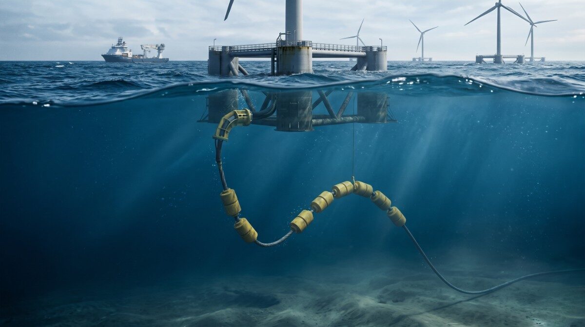
Executing the marine installation of these intricate electrical lifelines demands exceptional precision from cable-laying vessels and support spreads. Laying dynamic cables, attaching buoyancy modules at exact water-depth intervals, and executing platform pull-ins through submerged fairleads require narrow operational weather windows. These complex marine campaigns highlight why developers must integrate marine cable logistics directly into comprehensive offshore wind turbine installation planning under weather constraints to minimize offshore vessel standby costs and prevent weather-related structural damage.
The transition from medium-voltage inter-array connections to high-voltage dynamic export infrastructure also introduces severe thermal management challenges. High electrical currents generate internal resistive heating that must dissipate through the cable layers into the surrounding ocean. In suspended lazy-wave sections, natural seawater convection provides effective cooling. However, where dynamic cables enter sealed platform J-tubes or transition into buried seabed trenches, elevated thermal resistivity can cause localized overheating. Engineers utilize dynamic thermal rating systems that combine optical distributed temperature sensing with computational fluid dynamics to calculate allowable conductor ampacity in real time.
Digital Health Monitoring and Life Extension Strategies
Once dynamic cables are commissioned subsea, physical access for manual inspection is severely constrained by water depth, high currents, and operational safety boundaries. Subsea operators are embedding distributed fiber-optic sensing technology directly into dynamic cable cross-sections to achieve real-time health monitoring.
Distributed temperature sensing allows operators to monitor conductor thermal profiles continuously, pinpointing electrical hotspots or localized heating that could indicate insulation breakdown. Distributed acoustic sensing detects abnormal vibrations, mechanical strumming caused by vortex-induced vibration, and external impacts from maritime traffic or dropped objects. Concurrently, distributed strain sensing measures dynamic curvature and axial strain along the suspended lazy-wave profile.
Aker Solutions partnered with offshore sensor developers in 2025 to deploy integrated subsea condition-monitoring platforms for dynamic power systems. Sensor data streams into onshore digital twin models that continuously recalculate remaining cable fatigue life based on actual environmental loading rather than theoretical worst-case forecasts. PowerGen Advancement observes that by identifying fatigue hotspots and structural anomalies years before failure occurs, operators can adjust platform ballasting or schedule targeted subsea interventions during benign summer seas, extending the operational life of dynamic electrical transmission systems.
References
- “Floating Offshore Wind Dynamic Cables Joint Industry Project” – Carbon Trust
- “Subsea Power Cables for Offshore Wind DNV-ST-0359” – DNV
- “High Voltage Dynamic Export Cable Technology Validation” – Prysmian Group
- “Dynamic Cable Solutions for Floating Wind Commercial Arrays” – Nexans
- “Ancillary Systems for Floating Offshore Wind Dynamic Cables” – Trelleborg
- “Subsea Power Transmission and Lifecycle Management Review” – Aker Solutions