




















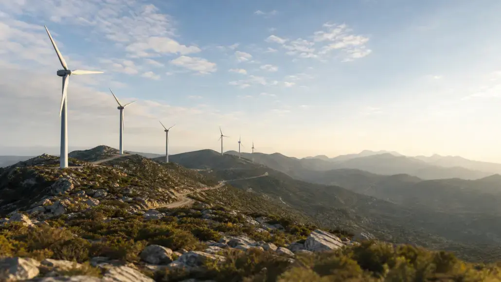
Onshore wind development faces a physical land constraint across mature renewable markets. Prime flatland sites with uniform wind conditions are largely developed, pushing developers into mountainous regions, forested ridges, and undulating landscapes. WindEurope data published in early 2026 confirmed that Europe added 19.1 GW of wind capacity in 2025, with onshore installations contributing 17.2 GW. A substantial portion of new European projects, particularly across the Iberian Peninsula, Scandinavia, and the Balkan corridors, occupies non-simple topography where standard flat-terrain aerodynamic assumptions do not apply.
Deploying multi-megawatt turbines in topographically varied landscapes creates complex microclimates. Hills, escarpments, and narrow valleys distort atmospheric boundary layers, generating steep vertical wind shear, localized flow separation, and severe turbulence. In this environment, complex terrain layout optimization has emerged as an essential engineering discipline. Developers can no longer rely on standardized geometric turbine grids. Siting mistakes that cause unexpected wake interactions or excessive mechanical loading can reduce annual energy yield by five to eight percent while drastically shortening the design life of mechanical components.
Aerodynamic Complexities of Non-Flat Landscapes
Traditional wind project engineering models assume linear atmospheric flow over gentle slopes. When wind flows over complex topography, several physical phenomena disrupt these assumptions:
- Topographic speed-up over ridgelines can accelerate wind velocity, but narrow hill crests often create severe cross-axis wind shear across large rotor diameters.
- Recirculation zones and flow separation on leeward slopes produce localized pockets of low-velocity, highly turbulent air.
- Thermal stratification in mountain valleys creates diurnal wind shifts, where cool katabatic nocturnal drainage flows reverse daylight wind vectors.
- Forestry canopy friction adds an elevated displacement height, stripping kinetic energy from the lower half of the rotor swept area.
When wake fields interact with these terrain-induced flows, the downwind turbine experiences compounding turbulence. The wake does not travel in a straight trajectory. Instead, it curves along topographic contours, rises over knolls, or sinks into depressions. In an unoptimized layout, a downstream turbine may operate inside an expanded wake cone where turbulent kinetic energy is magnified rather than dissipated.
The financial fallout is two-fold. Power production drops below pre-construction financial models, and the turbine experiences severe asymmetric fatigue loads. The International Energy Agency noted in its Renewables 2025 analysis that operational efficiency and capital preservation are central to project profitability in merchant-exposed markets. Protecting drivetrain assets begins with proper micro-siting during the initial spatial design phase.
Advanced Computational Fluid Dynamics and Wake Steering
Overcoming complex terrain challenges requires a shift away from linear flow software toward high-resolution computational fluid dynamics. Engineering teams increasingly utilize three-dimensional Reynolds-Averaged Navier-Stokes models coupled with mesoscale weather prediction systems. For sites characterized by extreme slopes, Large Eddy Simulation tools model transient vortex shedding and intermittent gust structures that standard steady-state equations miss.
Modern micro-siting workflows pair these fluid dynamics tools with automated layout optimization algorithms. Genetic algorithms and particle swarm optimization evaluate millions of spatial coordinate combinations across the digital elevation model. Rather than maximizing gross wind resource exposure in isolation, these algorithms solve multi-objective objective functions:
- Maximizing net electrical yield by balancing wind speed-up against terrain roughness.
- Minimizing wake deflection and wake overlap across seasonal prevailing wind directions.
- Enforcing strict mechanical fatigue thresholds defined under the International Electrotechnical Commission standard IEC 61400-1 for site suitability.
- Constraining turbine coordinates to viable geotechnical corridors to keep civil balance of plant costs within budget.
Active wake control, specifically wake steering through intentional yaw misalignment, has become an integral consideration during the spatial layout phase. By yawing upstream turbines a few degrees away from the incoming wind vector, operators deflect the downstream wake core away from trailing rotors. In complex terrain, where natural valleys or ridge geometries funnel air along fixed vectors, coordinated wake steering layouts increase park-level energy production by two to four percent compared to uncoordinated operations.
Terrain-Aware Civil and Electrical Infrastructure Planning
Optimizing a wind farm layout in steep topography involves balance of plant logistics alongside aerodynamic modeling. The windiest ridge is useless if the civil construction expenditure required to reach it destroys project economics. Modern layout software integrates geographic information systems to evaluate slope angles, soil bearing capacities, and heavy transport turning radiuses.
Turbine positions must align with road construction grading limits, crane pad dimensions, and medium-voltage cable trenching corridors. A layout that achieves two percent higher aerodynamic yield but requires extensive cut-and-fill earthworks on unstable rocky slopes can increase balance of plant capital expenditure by millions of euros. Layout optimization platforms calculate these civil trade-offs concurrently, evaluating the net present value of every proposed turbine coordinate over a thirty-year operating life.
Grid connection corridors and internal collector networks also dictate micro-siting geometry. Routing underground cables across rocky gullies, waterways, and fault zones introduces severe cost escalations and operational risks. Optimized layouts cluster turbines to minimize trenching distances and reactive power losses while preserving necessary aerodynamic separation distances.
Balancing Structural Integrity with Yield Generation
The ultimate objective of complex terrain layout optimization is finding the optimal point between maximum electrical generation and acceptable mechanical fatigue. Turbines sited on high ridges experience severe inflow angles, where the wind vector strikes the rotor plane obliquely. This creates alternating aerodynamic bending moments on the blades and main shaft during every rotation.
When turbines are placed on ridge lines and complex slopes, severe flow separation and localized turbulence accelerate mechanical degradation, making Wind Turbine Condition Monitoring Through Acoustic Emission Analysis an indispensable operational safeguard for early flaw detection.
To address these extreme site-specific loads, wind farm developers frequently deploy mixed-turbine configurations across a single project boundary. A wind farm might utilize larger rotors with lower tip-speed ratios in sheltered valley depressions where wind speeds are moderate and turbulence is low, while deploying reinforced, smaller-rotor Class S turbines along high-exposure hilltops to withstand severe gusting and shear.
Site-specific optimization also factors in curtailment strategies. Dynamic sector management algorithms instruct specific turbines to derate or curtail operations during narrow wind direction and atmospheric stability windows when turbulence intensity exceeds structural design limits. This operational flexibility allows developers to place turbines closer together in productive zones without breaching manufacturer warranty requirements.
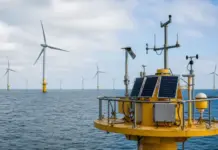
Data validation using multi-point scanning LiDAR systems is transforming the layout design phase. Rather than relying on a single meteorological mast, developers deploy pulsed scanning LiDAR devices that map three-dimensional wind fields across undulating terrain over twelve-month campaigns. Feeding empirical volumetric wind data directly into optimization software eliminates uncertainty in numerical simulations, allowing investors to underwrite project financing with higher confidence and tighter P90 debt sizing margins.